
Choosing a Process Gas Solenoid Valve starts with understanding the gas, operating conditions, and purpose of the line. A valve that works well with dry nitrogen may not suit a hot, corrosive, or moisture-bearing gas. Small details matter. Check the gas composition, pressure range, temperature, required flow, and how often the valve will switch. These figures should come from the actual process, not a rough estimate on a sticky note.
Next, compare body and seal materials with the gas and expected service conditions. Confirm that the valve’s pressure rating covers both normal operation and foreseeable changes. Consider response time, port size, coil voltage, enclosure, and whether the valve should open or close when power is lost. That last choice can shape the safety of the system. Do not select by connection size alone. Two valves with matching ports can behave very differently under real flow.
Manufacturer data sheets and qualified engineering review help turn these checks into a defensible choice. Ask for test conditions behind flow and leakage figures, and confirm compatibility for the exact gas mixture. A catalog description may leave useful questions unanswered. That is worth noticing, not guessing past. This guide explains how to assess the key specifications, compare valve designs, and avoid common selection errors. The best choice is not always the most expensive or sophisticated one. It is the valve whose documented limits match the process, with enough margin for the conditions you can reasonably expect.
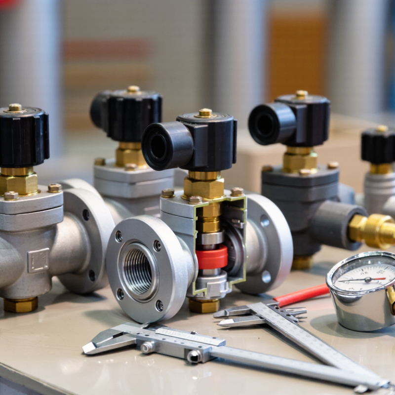
A process gas solenoid valve uses an electrical signal to open or close a gas path. It can start a burner, isolate a line, or coordinate gas delivery with other equipment. It is a gatekeeper. Unlike a flow-control valve, a standard solenoid valve usually switches between open and closed positions; it does not precisely meter flow. Its response depends on coil voltage, pressure differential, gas compatibility, and the valve’s internal design. A small seat leak can matter when the valve must provide tight shutoff.
During selection, engineers should check operating pressure, temperature, required flow, cycle frequency, and the specified fail position.
The IEA’s Global Methane Tracker 2024 estimates that fossil-fuel operations emitted about 120 million tonnes of methane in 2023. This is not a valve-specific figure, but it highlights why containment deserves attention.
At commissioning, verify the electrical signal, inspect connections, and perform an appropriate leak test. A valve that works on a bench may behave differently in a vibrating, hot installation.
Sizing is not always perfect; actual pressure conditions can expose that gap. Choose for the real process, not just the catalogue numbers.
Gas compatibility starts with the actual stream, not the valve catalogue. Record gas composition, moisture, pressure, temperature, and cleaning requirements. Small traces of water can change corrosion behavior. Oxygen service also demands clean, oxygen-compatible components; a material suitable for air may not be suitable for oxygen.
For the body, 316 stainless steel is a common starting point, not a universal answer. ASTM A240/A240M specifies 2.0–3.0% molybdenum for 316 stainless steel, which can improve resistance to some corrosive environments. Check the full gas mixture before selecting it. Hydrogen service needs particular care because some metals can lose ductility under certain conditions. Seal choice matters too: elastomers may swell, harden, or leak when exposed to a gas. Verify compatibility at the operating temperature and pressure, then test the assembled valve if the service is critical.
Phase conditions can complicate the choice. The NIST Chemistry WebBook reports carbon dioxide’s critical point as 304.13 K and 7.38 MPa; near that region, density and flow behavior change sharply. This is easy to overlook. I would also recheck seal data against real operating cycles, since a static compatibility chart may not reflect repeated pressure changes. Use the current ASTM material specification and NIST property data as references, then confirm the final selection with a qualified materials engineer.
Matching Pressure, Flow Rate, and Operating Conditions
Start with the gas supply pressure and the pressure downstream of the valve. The difference between them affects whether the valve can open and how much gas it can pass. Check the valve’s minimum and maximum operating pressures, not just the pipeline’s normal reading. A gauge can fluctuate during startup, so allow for realistic peaks and drops.
Next, match the required flow rate to the valve’s capacity. A valve that is too small may restrict the process; one that is oversized can make flow control less stable. Review the manufacturer’s flow data for your gas and operating pressure. Also confirm compatibility with the gas, seals, and body materials. Temperature, humidity, dust, and switching frequency matter, too. Small details count.
How to Choose a Process Gas Solenoid Valve
Selecting the right valve starts with the gas, operating pressure, temperature, and required flow. Check wetted materials against the gas supplier’s compatibility guidance. A seal that works well with one gas may swell or become brittle with another. Choose a valve type suited to the process: direct-acting models can work at low pressure, while pilot-operated designs often need a minimum pressure differential. Confirm the valve’s pressure range and flow capacity in its technical data, not just its port size. Small details matter.
Voltage selection should match the available power and control system. Verify whether the coil requires AC or DC, and check its rated voltage, frequency, and duty cycle. A mismatch may cause overheating, slow switching, or failure to open. Consider the required default state, too. A normally closed valve stops flow when de-energized; a normally open valve behaves differently. The safer choice depends on the process and its hazard review. Don’t guess from wire colors.
Tips: Check the datasheet and wiring diagram before installation. Confirm the coil connector, ambient temperature rating, and pressure limits. If the gas composition or operating conditions may change, ask a qualified process engineer to review the selection. Even a careful checklist can miss an assumption; record what you still need to verify.
| Selection Factor | Common Options | When to Consider It | Checks Before Selection |
|---|---|---|---|
| Valve function | Normally closed (NC), normally open (NO), or latching | NC valves close when de-energized and are often used where loss of power should stop flow. NO valves may suit applications where flow should continue without power. Latching valves change state with a pulse and retain their position without continuous coil power. | Define the required state during power loss and confirm that the valve’s actual fail position meets the process safety design. |
| Valve type | Direct-acting or pilot-operated | Direct-acting designs operate the seal using the coil and can generally work without a minimum pressure differential. Pilot-operated designs use process pressure to assist opening and are commonly considered for larger flow capacities. | Check minimum and maximum operating pressure, pressure differential, flow capacity, response requirements, and whether the process can provide the pressure needed for pilot operation. |
| Port arrangement | 2/2-way (two ports, two positions) or 3/2-way (three ports, two positions) | A 2/2-way valve starts or stops flow in a line. A 3/2-way valve can switch a port between supply and exhaust, depending on its configuration, and may be used for actuating or venting circuits. | Match the port count, flow path, connection size, and normal position to the piping and control schematic. |
| Coil voltage and power | Common coil ratings include 12 or 24 V DC and 24, 110/120, or 220/230 V AC; availability varies by valve | Choose a rating compatible with the control supply. DC coils are commonly used with electronic controls; AC coils may be used where an AC supply is available. | Match the rated voltage, AC frequency where applicable, coil power, connector, and duty rating to the supply and control system. Do not energize a coil at an incompatible voltage. |
| Wetted materials and seals | Body and internal materials vary; seal materials may include elastomers or other compounds selected for the service | Material choice depends on gas composition, moisture, contaminants, temperature, pressure, and required leakage performance. | Confirm chemical compatibility and operating limits with the valve documentation. Do not assume a valve is suitable for every gas based only on its body material. |
| Pressure and flow | Specified by the valve’s rated pressure range and flow data | Process conditions determine whether the valve can open, close, and deliver the required flow reliably. | Compare actual inlet and outlet pressures, differential pressure, required flow, and temperature with the manufacturer’s ratings for the exact configuration. |
| Electrical and environmental protection | Enclosure or connector protection ratings vary by construction | Protection against dust or water ingress may be important in exposed or washdown locations. Hazardous areas require equipment approved for the applicable area classification. | Check the complete installed assembly’s protection rating, ambient-temperature limits, wiring method, and any required hazardous-area approvals. |
| Safety and system integration | De-energized position, manual override, position indication, and system-level shutoff provisions | These features may help with testing, troubleshooting, or meeting a process safety design, but they do not replace a system-level risk assessment. | Verify the required fail state, allowable leakage, response time, maintenance plan, and applicable codes or approval requirements for the installation. |
| Final selection check | Confirm gas compatibility, pressure and temperature limits, flow capacity, voltage, connection details, and required approvals against the documentation for the exact valve model and configuration before installation. | ||
Choosing a process gas solenoid valve starts with operating conditions, not just pipe size. Record gas composition, pressure range, temperature, flow direction, and required response time. Check wetted materials against the gas and cleaning chemicals; compatibility can change with mixtures or temperature. Confirm coil voltage and enclosure rating suit the control panel and installation area. Small details matter. Support nearby tubing to prevent vibration from stressing fittings, and leave room to remove the coil.
Check documents for process-gas suitability, pressure and temperature limits, electrical ratings, and certifications required for your site and region. Match the stated ratings to actual operating conditions, including pressure surges. Do not guess. During maintenance, isolate the line according to site procedures, inspect seals and wiring, and use an approved leak-check method. Test valve operation after servicing. Set inspection intervals from operating conditions and the equipment maker’s guidance; a fixed schedule may not fit every duty cycle. Keep records of checks, replacements, and observed faults.
Tips: Verify the flow arrow before tightening connections. Photograph wiring before removal. If the gas composition or duty cycle changes, review material compatibility and maintenance intervals again. I still double-check documentation against the installed configuration; paperwork alone can miss a field change.
