
Choosing the right Tnc Cable Assembly is not just a matter of matching connector ends. A cable may fit securely and still introduce excessive signal loss, poor shielding, or an unreliable connection. The details matter. A threaded TNC coupling can help resist loosening under vibration, but the complete assembly must suit the equipment and operating conditions.
Start with the system’s impedance, usually 50 ohms, and confirm its frequency range. Then consider cable type, length, connector gender, and the space available for installation. A long run of thin cable may cause more attenuation than expected. In a crowded equipment cabinet, a stiff cable can also place unwanted strain on its connector. Check manufacturer specifications for insertion loss, VSWR, shielding, temperature range, and bend limits. Where performance is critical, test the finished assembly in the intended setup. Datasheet values alone may not reveal every installation issue.
A useful selection principle is: “Match the assembly to the system, then verify it in its real operating conditions.” No source article or verifiable expert quotation was provided, so this introduction does not assign that line to a named specialist. That restraint matters; invented attribution can make technical guidance less trustworthy. Even careful selection has limits. Actual results depend on connectors, cable construction, routing, and installation quality. A small detail, such as a tight bend near the connector, can change the outcome.
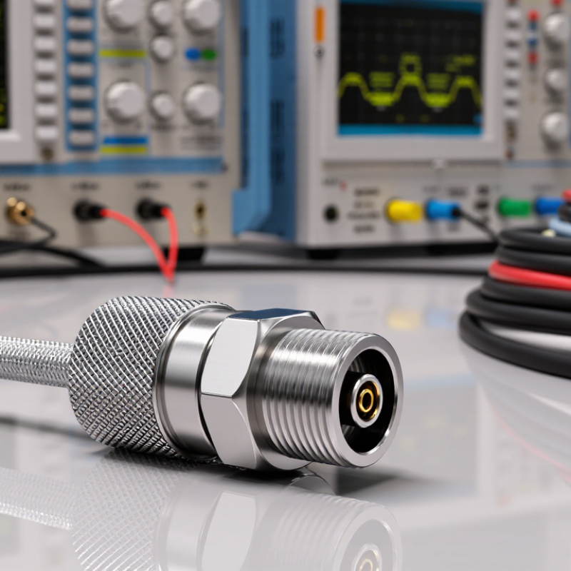
A reliable TNC cable assembly starts with the electrical job, not the connector alone. Record the system impedance, operating frequency, and peak power before comparing options. TNC assemblies are commonly 50 ohms, but 75-ohm versions exist; confirm that both ends match the equipment. Small mismatches matter. At higher frequencies, request insertion-loss and return-loss data across the full operating band, not just at one test point. Check shielding and connector sealing if the cable will run near motors, outdoors, or through damp enclosures. Power ratings can also change with frequency, temperature, and cable length.
Next, map the cable’s actual route. Note its required length, the space behind each panel, and any tight bends near the connectors. A cable that fits on a bench may kink inside a cabinet. Respect the cable maker’s minimum bend radius, and consider strain relief where vibration or repeated movement could pull on the TNC interface. Measure twice. Connector gender, straight or right-angle orientation, and bulkhead mounting details can affect whether the assembly fits without twisting.
Temperature range, jacket durability, and exposure to oil or moisture deserve attention too. Specify these conditions rather than choosing a cable by appearance. In practice, one requirement is easy to overlook: installation access. A connector may meet every electrical target yet be awkward to tighten in a crowded rack. That trade-off is worth reviewing before ordering, even when the final route is not perfectly predictable.
A TNC assembly should match the impedance of the entire RF path, not just the connector. Most TNC systems use 50 ohms, while some video and instrumentation paths use 75 ohms. Mixing them creates a measurable mismatch. For an ideal 50-to-75-ohm step, the reflection coefficient is 0.20, with a 1.5:1 VSWR and about 14 dB return loss. That can reduce delivered signal power and distort sensitive measurements. Check the equipment ports, cable, and termination before ordering.
Frequency ratings need the same careful check. IEC 61169-17:2011 specifies the TNC connector interface, but the connector’s rating alone does not establish the assembly’s usable bandwidth. Many 50-ohm TNC designs are rated to 11 GHz; the cable, termination, and assembly workmanship can lower that limit. At higher frequencies, even a small mismatch or poorly fitted connector can affect test results. Look for a stated frequency range and return-loss or VSWR data for the complete assembly. I would not rely on a connector headline rating by itself; that shortcut is tempting, but incomplete. A small detail? Cable length and bend position can also change performance in a real installation.
How to Choose the Right TNC Cable Assembly?
Select a Cable Type for Signal and Installation Needs
Start with the signal path, not just the connector. Most TNC RF assemblies use a 50-ohm impedance, so match the cable and equipment to avoid reflections. IEC 61169-17:2022 defines the TNC connector interface, but it does not guarantee the loss of a finished cable assembly. Ask for attenuation data at your operating frequency and actual cable length. A loss figure without a test frequency tells you little.
For short equipment links, flexible RG-58 is often practical. Longer runs or higher frequencies may call for a larger, lower-loss coaxial cable; small cables such as RG-316 are easier to route, but can have greater attenuation. Check the supplier’s attenuation figures in dB per 100 metres, minimum bend radius, and power rating. Then account for the real installation: a cable bent sharply behind a cabinet can stress its termination, while an outdoor run needs a jacket rated for exposure. Check the whole path. MIL-STD-348B provides connector interface dimensions, but the assembled cable’s performance still depends on cable choice, termination, and handling. Specs help; they do not replace checking the installed route.
Compare typical cable outer diameters to help match a TNC assembly to your installation space and flexibility needs.
How to use this chart: Smaller-diameter cables are often easier to route through tight spaces, while larger cables may be preferable when lower signal loss or greater physical robustness is needed. Actual performance depends on cable construction, frequency, and length; confirm the cable’s specifications and TNC connector compatibility before selecting an assembly.
Choosing a TNC cable assembly means looking beyond its threaded coupling. The connector body material affects strength, weight, and corrosion resistance. Brass is common, while stainless steel may suit damp or corrosive locations. Plating matters too. Check the specified finish and its compatibility with the mating connector. Small details matter. A finish may look fine indoors but show wear after repeated handling.
Read environmental ratings for the complete assembly, not just the connector. An IP rating applies only under stated test conditions and may depend on proper mating and sealing. TNC connectors are not automatically waterproof. Not automatically. Check the temperature range, humidity limits, and any resistance to salt spray or vibration. Match those details to the actual installation, such as a sunlit rooftop or a cabinet that collects condensation.
The cable jacket needs equal attention. PVC may work indoors, but outdoor runs often need UV-resistant material; oil exposure can require a different jacket. Confirm that the cable and connector share compatible temperature and environmental limits. I have seen selections focus on metal type alone, which misses the seal and jacket. That oversight is easy to make. Review the assembly datasheet, and leave some margin for harsher conditions than expected.
| Selection Factor | Option or Rating | Typical Characteristics | When to Consider It | What to Verify |
|---|---|---|---|---|
| Connector body | Nickel-plated brass | Common choice offering a balance of strength, machinability, and corrosion protection in ordinary indoor conditions. | General-purpose equipment and protected installations. | Plating type and thickness, base material, and suitability for the site’s humidity or chemical exposure. |
| Connector body | Stainless steel | Provides greater resistance to corrosion and mechanical wear than many plated-brass finishes; usually costs more and may be heavier. | Corrosive, washdown, marine, or demanding outdoor environments, when the assembly is designed for them. | Steel grade, mating-contact materials, and compatibility with nearby metals and chemicals. |
| Center contact and finish | Plated conductive contacts | Contact base metal and plating affect conductivity, wear, and corrosion behavior. Gold plating is used on some contacts; it is not a substitute for proper sealing. | Repeated mating, low-level signals, or environments where contact stability matters. | Contact finish, mating-cycle rating, and compatibility with the counterpart connector. |
| Insulator | PTFE or another specified dielectric | The dielectric supports electrical isolation and influences the connector’s RF performance and temperature limits. Material choice alone does not establish a complete assembly rating. | RF applications where the required frequency range and operating conditions are known. | Specified operating temperature, frequency range, impedance, and electrical ratings for the complete assembly. |
| Cable-entry seal | Elastomer grommet or cable seal | Helps limit moisture and dust entry at the cable end when correctly matched to the cable diameter and installed as specified. | Outdoor or dusty installations that require a sealed cable entry. | Seal material, supported cable diameter, installation method, and resistance to the actual fluids and temperature range. |
| Mating-interface seal | Gasket or O-ring, where specified | Can help seal the mated interface when used with a compatible connector pair and tightened correctly. A threaded TNC coupling does not by itself guarantee a waterproof connection. | Exposed connections subject to rain, spray, or washdown. | Whether the seal is included, the required mating hardware, and the tested condition of the mated connection. |
| Ingress protection | IP rating, if documented | An IP rating applies to a defined tested configuration. It should not be assumed from the TNC interface alone and may depend on mating, cable entry, and installation details. | Installations with specified dust or water exposure requirements. | Exact IP code, test conditions, mated or unmated status, and whether the rating covers the full cable assembly. |
| Temperature and chemicals | Assembly-specific limits | Temperature capability and chemical resistance vary with the connector, seal, cable jacket, and termination materials. | High or low temperatures, oils, cleaners, fuels, or other chemical exposure. | Operating and storage limits, chemical compatibility, and ratings for the complete cable assembly. |
| Vibration and retention | Threaded TNC coupling | The threaded coupling provides positive mechanical retention and is generally less prone to accidental release than a push-on connection. | Equipment subject to movement or vibration, provided the assembly is properly installed. | Required torque or installation method, cable strain relief, and any vibration qualification for the specific assembly. |
| Final selection | Match the complete assembly to the application | TNC specifies a connector interface; performance and environmental protection depend on the selected cable, terminations, materials, seals, and installation. | All installations, especially those exposed to moisture, vibration, or corrosive conditions. | Confirm impedance, frequency range, cable type, connector gender, mating compatibility, and documented environmental ratings before ordering. |
Choose a TNC cable assembly by matching it to the equipment and operating conditions. Check connector gender, impedance, cable length, and the frequency range. Do not assume every TNC assembly uses the same impedance; confirm the equipment specifications. If the cable will run outdoors or near moving parts, check its jacket rating and flexibility too. Small mismatches can cause connection problems.
Then review performance data. Compare insertion loss and VSWR across the frequencies you actually use, not just a headline maximum. Check shielding and power-handling ratings against your application. Ask for test results or a datasheet that identifies the assembly and its tested range. Quality documentation matters. A polished label alone proves little. It is easy to focus on connector fit and overlook cable loss, especially on longer runs.
Tips: Measure the installed route before ordering. Leave room for gentle bends, and avoid pulling the cable tight. Confirm that samples or production units meet the same stated specifications. A checklist helps, but it can still miss a detail; verify critical requirements with the supplier before installation.
