
Automated Dispensing Robot Videos

A World of Robotic Dispensing and Assembly Solutions

What Is a Grid On Inverter and How Does It Work?

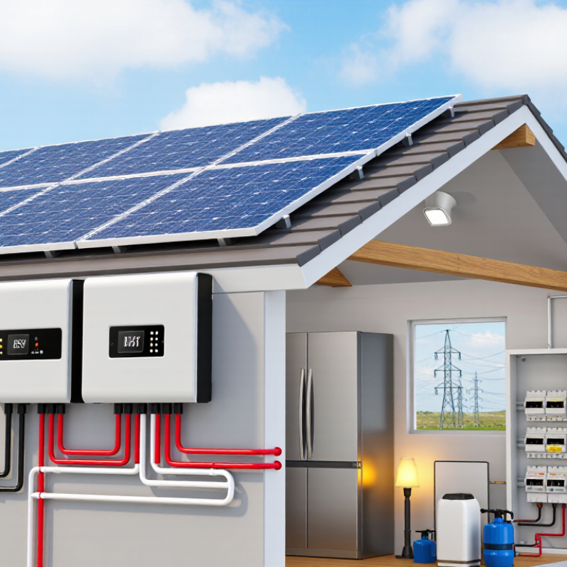
A Grid On Inverter connects a solar power system to the public electricity network. It converts direct current from photovoltaic panels into alternating current for household or commercial use. The inverter also matches the grid’s voltage, frequency, and phase. This coordination keeps appliances operating normally and allows surplus energy to flow outward, where local rules permit.

The process begins when solar panels produce electricity under daylight. Sensors measure the grid waveform many times each second. The inverter then adjusts its output to follow that waveform closely. Power first serves nearby loads, such as refrigerators, pumps, or lighting. Extra generation may pass through a bidirectional meter. During cloudy periods or at night, electricity comes from the grid instead. There is no mystery here, but the control process is highly precise.

A key safety feature is anti-islanding protection. If the utility supply fails, a compliant inverter normally stops exporting power. This protects repair crews working on supposedly de-energized lines. Proper installation also requires suitable cables, grounding, surge protection, and professional commissioning. Requirements differ between regions and utility companies. Checking approval documents matters.

Real-world performance depends on shading, panel temperature, roof direction, and system sizing. A clean data screen can still hide poor installation. That deserves attention. This guide explains the main components, operating stages, benefits, limitations, and selection factors behind a Grid On Inverter. It also examines common misunderstandings, including backup power assumptions. A grid-connected inverter is efficient, but it is not automatically an emergency power source.
What Is a Grid On Inverter and How Does It Work?

Definition and Basic Purpose of a Grid-Tied Inverter

A grid-tied inverter, also called an on-grid inverter, connects solar panels to the public electricity network. Its basic purpose is simple: convert direct current from the panels into alternating current for household use. The inverter matches the grid’s voltage, frequency, and phase. This allows solar electricity to power lights, refrigerators, pumps, and other connected loads.

When the panels produce more electricity than the building needs, the extra power can flow into the grid, if local rules and equipment allow it. When solar production falls, electricity comes from the grid as usual. The inverter constantly measures these changes. It does not usually store energy, because standard grid-tied systems need the utility network as a reference.

A critical function is anti-islanding protection. If the grid fails, the inverter must stop exporting power. This protects repair workers from unexpected electricity on a supposedly isolated line. Proper installation also requires approved equipment, correct wiring, inspection, and utility permission. Requirements vary by location.

In real installations, the concept looks easy. The wiring is not. A small setting error can reduce output or trigger shutdowns. Shading, loose connections, and voltage changes also affect performance. Technicians check production data and electrical measurements instead of trusting the display alone. That lesson is easy to overlook. A grid-tied inverter is not merely a converter; it is a controlled interface between private generation and the wider power system.

What Is a Grid-On Inverter and How Does It Work?

A grid-tied inverter converts DC electricity from a solar array into AC electricity synchronized with the utility grid. The waveform below shows one 50 Hz cycle of a typical 230 V RMS grid system and an inverter delivering 10 A RMS at unity power factor.

How to read the chart: The inverter matches the grid voltage frequency and phase so its AC current can flow safely into the building loads or the electrical grid. At unity power factor, the current waveform is in phase with the voltage waveform, representing approximately 2.3 kW of active power.

Main Components and Internal Energy Conversion Process

A grid on inverter connects a renewable energy source to the public electricity network. Its main task is converting variable direct current into stable alternating current. Solar panels may produce 38 volts at one moment and 31 volts later. The inverter continuously tracks this changing output through maximum power point tracking, or MPPT. It is not magic. A control board measures voltage, current, frequency, and phase many times per second.

Inside the unit, incoming DC passes through protection circuits and switching devices. These switches turn the current on and off at high speed, creating a controlled waveform. A DC-link capacitor temporarily smooths energy between the input and switching stage. This small storage point matters when sunlight changes quickly. The output then passes through inductors and capacitors that remove high-frequency electrical noise. Some systems also use a transformer, although many modern designs avoid one to reduce size and losses.

A synchronization controller compares the inverter waveform with the grid waveform. It adjusts timing before sending power outward. If the grid frequency or voltage moves beyond safe limits, the inverter disconnects automatically. This anti-islanding function protects repair workers and nearby equipment. Heat sinks and temperature sensors manage heat from switching losses. The process sounds tidy on paper, but real conditions are less predictable. Dust, weak wiring, shading, and rapid cloud movement can reduce efficiency. A useful design review should examine these details, not only the rated output.

What Is a Grid On Inverter and How Does It Work? - Main Components and Internal Energy Conversion Process
Stage Main Component Primary Function Internal Energy Conversion or Control Process Typical Technical Data
1 DC Input Terminals Receive direct current from photovoltaic modules, batteries, or another DC source. Transfers incoming DC power to the inverter's input protection and conditioning circuits. Input voltage may range from approximately 100 V DC to 1,000 V DC, depending on system design.
2 DC Disconnect and Protection Provides isolation and protection against overcurrent, short circuits, and maintenance hazards. Does not normally convert energy; it interrupts or limits the DC power path when a fault or service condition occurs. May include fuses, circuit breakers, surge protective devices, and a manually operated disconnect.
3 EMI and Input Filtering Reduces conducted electrical noise and smooths high-frequency disturbances on the DC input. Uses inductors, capacitors, and other passive components to attenuate unwanted frequencies without changing the nominal DC voltage. Filter design is selected according to switching frequency, power rating, and electromagnetic compatibility requirements.
4 DC-Link Capacitor Stores short-term electrical energy and stabilizes the internal DC bus. Buffers the difference between incoming source power and the rapidly changing power demand of the switching bridge. The DC-link voltage is commonly higher than the required AC RMS voltage and contains controlled voltage ripple.
5 Power Semiconductor Switching Bridge Creates a controlled AC waveform from the internal DC bus. Rapidly switches semiconductor devices, such as insulated-gate bipolar transistors or MOSFETs, using pulse-width modulation. Switching frequencies commonly range from several kilohertz to tens of kilohertz, depending on topology and power level.
6 Output Inductor and AC Filter Smooths the switched waveform and reduces high-frequency current ripple before grid connection. Filters the high-frequency components of the PWM waveform so that the output current more closely follows a sinusoidal waveform. The filter is designed for the system's rated current, switching frequency, grid frequency, and allowable harmonic distortion.
7 Grid Synchronization Control Matches the inverter output with the utility grid's voltage, frequency, and phase. A phase-locked loop or similar control algorithm measures the grid waveform and generates a synchronized reference signal. For a 50 Hz or 60 Hz grid, the inverter continuously tracks frequency and phase before and during power export.
8 Current and Voltage Sensors Measure DC input voltage, DC-link voltage, AC voltage, output current, and temperature-related operating conditions. Converts electrical measurements into feedback signals used for regulation, protection, power control, and fault detection. Measurement accuracy and sampling rate affect current control, efficiency, protection response, and power-quality performance.
9 Digital Control Processor Coordinates maximum power extraction, current regulation, grid support, and protective functions. Processes sensor feedback and adjusts switching commands so DC power is converted into controlled AC power. Control functions may include maximum power point tracking, reactive power control, ramp-rate control, and fault logging.
10 AC Output Protection Protects the inverter, wiring, and grid interface from abnormal current and voltage conditions. Does not intentionally convert energy; it disconnects or limits the AC output during unsafe operating conditions. Protection may include overcurrent, overvoltage, undervoltage, overfrequency, underfrequency, and surge protection.
11 Anti-Islanding Protection Prevents continued energization of a utility circuit when the grid is unavailable. Detects abnormal grid conditions or active changes in the interface and rapidly ceases power export when required. Grid-connected inverters are designed to stop supplying power within the response time required by applicable grid-interconnection standards.
12 Thermal Management System Keeps semiconductors, capacitors, and magnetic components within their permitted operating temperatures. Removes heat generated by conduction and switching losses using heat sinks, natural convection, forced-air cooling, or liquid cooling. Operating temperature limits vary by component and design; excessive heat can reduce output power and service life.
13 AC Grid Interface Delivers synchronized active power and, where supported, reactive power to the utility network. The filtered AC current is injected into the grid at the commanded phase angle, allowing control of real and reactive power. Common systems operate at single-phase or three-phase AC voltage and at either 50 Hz or 60 Hz, according to local requirements.
14 Monitoring and Communication Interface Reports operating status, energy production, alarms, grid conditions, and maintenance information. Does not perform power conversion; it transfers measured data to a display, controller, or monitoring platform. Typical data includes DC voltage, AC voltage, current, power, frequency, efficiency, temperature, and fault codes.
Energy Flow Summary: The inverter receives DC power, conditions and stabilizes the DC link, uses high-speed semiconductor switching to synthesize AC power, filters the waveform, synchronizes it with the utility grid, and exports controlled current while continuously monitoring safety conditions.

How a Grid-Tied Inverter Synchronizes With the Utility Grid

What Is a Grid-Tied Inverter and How Does It Work?

A grid-tied inverter converts solar panels’ variable DC electricity into grid-compatible AC power. It does more than change voltage. A phase-locked loop measures the utility waveform several thousand times per second. The inverter then matches its phase, frequency, and voltage before sending controlled current into the circuit. The utility grid sets the rhythm. The inverter follows it.

The process begins with maximum power point tracking, which continually adjusts panel operation as sunlight changes. A current-control loop shapes the output into a clean sine wave. IEEE 1547-2018 also requires modern interconnection equipment to manage abnormal voltage, frequency, and grid disturbances. Anti-islanding protection disconnects the inverter when utility power disappears. This prevents a private solar system from energizing lines during maintenance.

Scale makes reliable synchronization important. The IEA PVPS Trends in Photovoltaic Applications 2024 report recorded roughly 456 gigawatts of new photovoltaic capacity worldwide in 2023. That growth places more electronic converters on distribution networks. In practice, synchronization is not perfectly effortless. Harmonics, weak-grid conditions, measurement delays, and sudden cloud cover can challenge control systems.

Measurements are never perfect. A well-tested inverter responds within required limits, but installation quality still matters. Incorrect settings, loose connections, or poor grounding can create problems that software cannot fully correct. The U.S. National Renewable Energy Laboratory continues to identify inverter controls and grid integration as important research areas for high-renewable power systems.

Electricity Flow From Solar Panels to Household Loads

What Is a Grid On Inverter and How Does It Work?

Solar panels produce direct current (DC), but most household appliances use alternating current (AC). A grid on inverter performs this essential conversion. It also tracks the panels’ changing voltage and current to capture useful energy throughout the day. Sunlight reaches the roof, electricity travels through protective equipment, and the inverter creates synchronized AC power for the home.

Household loads receive solar electricity first. A refrigerator may start, lights may turn on, and other appliances draw power through the main distribution panel. When production exceeds demand, the remaining electricity can flow to the utility grid, subject to local rules and metering arrangements. When clouds reduce output, the grid supplies the shortfall. The inverter must match grid voltage and frequency carefully. If the grid fails, it normally disconnects automatically to protect repair workers. This means solar panels usually cannot power a home during an outage without approved backup equipment.

Tips: Keep panels clear of heavy dirt and shading. Check inverter status lights regularly, but do not open its enclosure. Ask a qualified electrician to inspect unusual sounds, heat, or error messages. Real systems are not perfectly efficient. Cable length, temperature, dust, and conversion losses reduce output. I have seen homeowners expect the panel rating every hour, which is unrealistic. Daily energy depends on weather, roof direction, season, and household habits. A simple energy monitor can reveal when solar power is used directly and when the home depends on the grid.

Safety Features, Benefits, and Common Operating Limitations

A grid-on inverter converts solar panels’ direct current into alternating current for a building and the public grid. It synchronizes voltage, frequency, and phase before exporting surplus electricity. This matters as solar expands: the IEA’s Renewables 2024 report projects about 5,500 GW of renewable capacity additions from 2024 to 2030. Solar and wind are expected to provide nearly 95% of that growth.

Safety comes first. Certified inverters monitor grid voltage and frequency continuously. If the grid fails, anti-islanding protection disconnects the inverter within a prescribed time. This prevents electricity from feeding damaged lines during maintenance. Many systems also detect ground faults, over-temperature conditions, and abnormal currents. Proper installation still matters. A compliant device cannot correct loose terminals, poor ventilation, or incorrect cable sizing.

The benefits are practical. Grid connection can reduce electricity purchases and avoid battery replacement costs. It also supports cleaner daytime power without large storage equipment. However, the system usually stops during a blackout. No backup power.

Operating limits deserve attention. Export rules, local voltage limits, and utility approvals vary by location. Long cables can cause voltage rise, while high panel output may exceed the inverter’s rated capacity. The IEA’s Electricity 2024 analysis highlights growing grid congestion and connection delays, which can restrict renewable projects. Curtailment may occur when the network cannot accept more power. The energy is then lost, sometimes unexpectedly. An installer should review annual production data, not only the inverter’s headline efficiency. That number rarely tells the whole story.